STEP400/STEP800
About
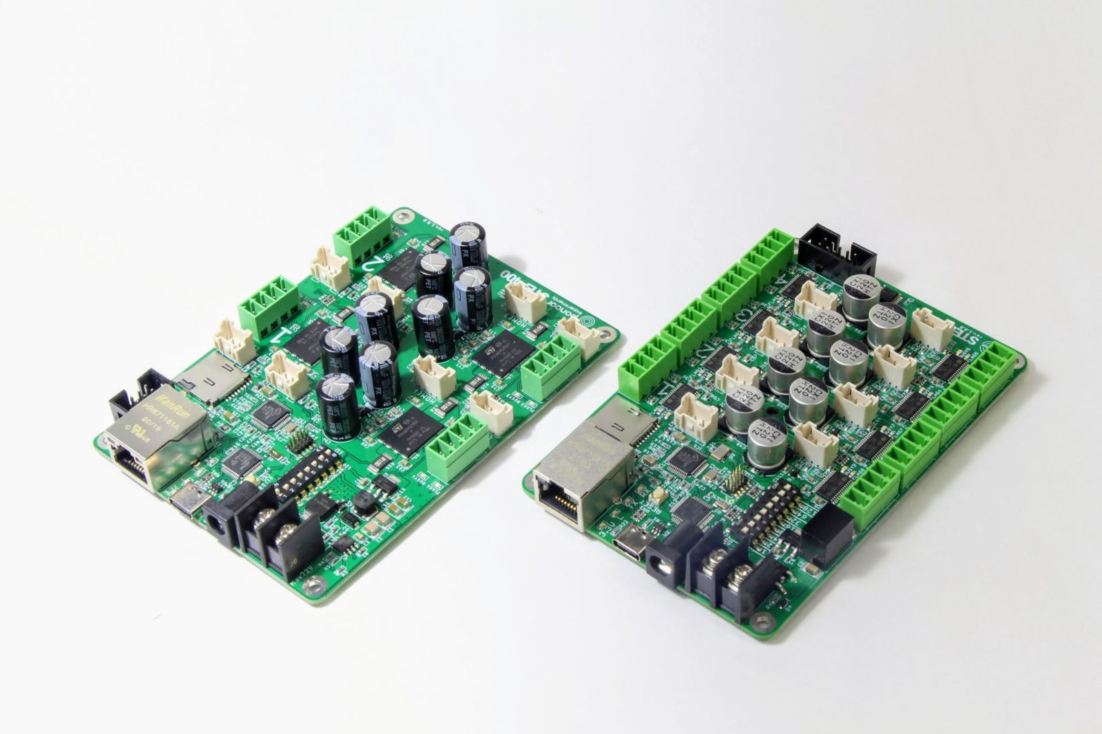
Both the STEP400 and STEP800 are multi-axis stepper motor controllers which can be controlled via Ethernet. While both devices use an Arduino Zero as the main control unit (MCU), the STEP400 uses STMicroelectronics’s powerSTEP01 as its stepper driver chip whereas the STEP800 uses STMicroelectronics’s L6470. It is recommended to review the datasheets for both chips to better understand how they work and what each command is doing.
Both devices use the exact same commands save for a select few which are marked in the API
Reference. So, unless you see STEP400 Only or STEP800 Only, assume the command is compatible
with both devices.
Getting Started
Example Files
The STEP400 and STEP800 both communicate via the Open Sound Control (OSC) protocol.
Beyond just python-step-series, a myriad of applications can also communicate with these
devices, so example configuration and setup files are provided in the list below:
Processing (thanks @yuskegoto)
openFrameworks (thanks @niimi)
Touch Designer (thanks @loveandsheep, @yuskegoto)
Node-RED (thanks @yuskegoto)
Wiring
Communication
Both devices communicate via Ethernet, meaning your computer must have an ethernet port or a USB-ethernet converter. This tutorial will assume you have connected the device directly to your PC (peer-to-peer); however, if this is not possible for you, then plugging the device into a network switch is also viable.
Please plug the ethernet cable in now.
Warning
Ensure your switch is actually a switch. Do not plug these devices into a router as router ports behave differently than switch ports do.
Note
Please do not power the device until directed to do so later in the tutorial. You will be asked to connect the power supply in the upcoming sections, but make sure it is not on.
Stepper Motors
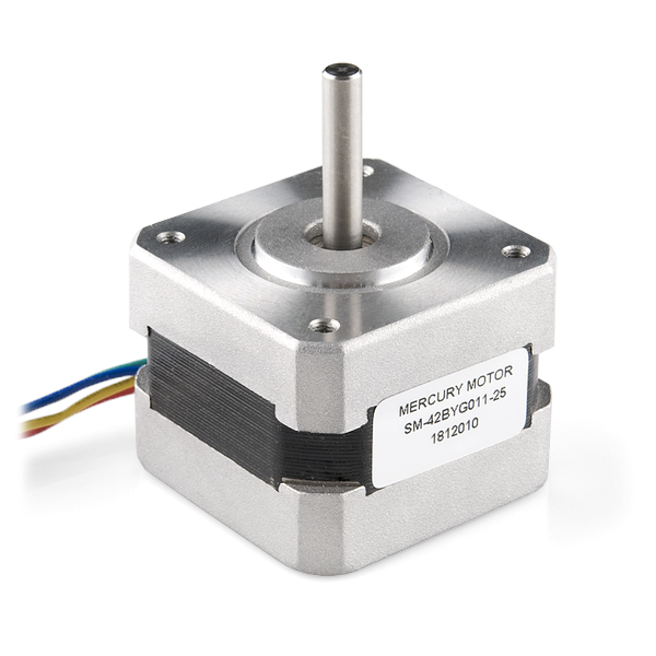
Only 4-wire, bipolar stepper motors can be used with these devices. As an example, a highly
accessible and inexpensive stepper motor is Mercury Motor’s SM-42BYG011-25. This tutorial
assumes you are using this motor, so, if you are not, you may need to watch out for specific
settings that may need to be changed to match the motor you have. The SM-42BYG011-25 can be
purchased from one the (unaffiliated) recommended sites below:
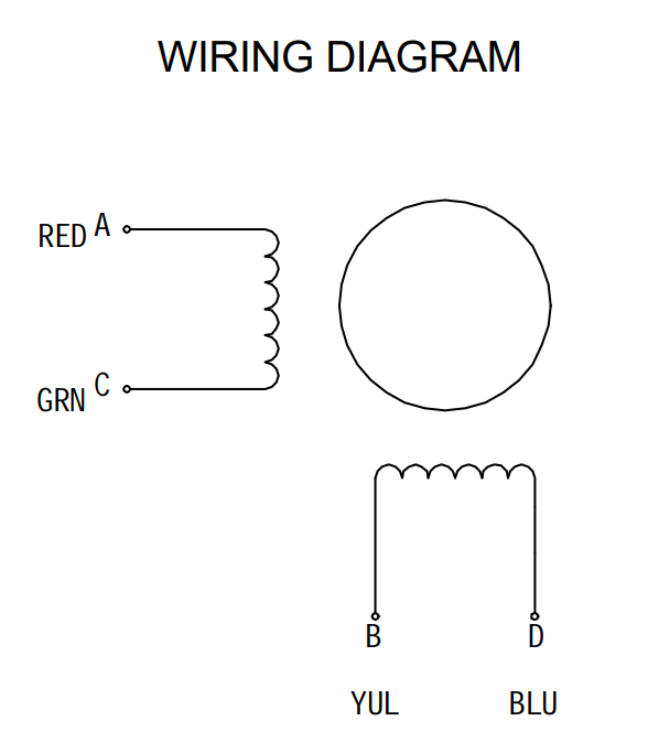
From the wiring diagram found in the datasheet for this motor, we can see that the wiring pairs
are Red - Green and Yellow - Blue.
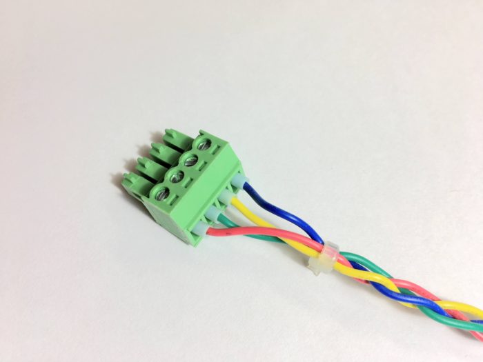
The wiring to the terminal block should look like this:
We’ve calculated register values for some motors and made them available as configuration files.
Power Supply
The STEP400 and STEP800 both have differing power ratings. These devices also have two different power input terminals. While the USB-C jack can be considered a power input terminal, it’s primary, and arguably sole purpose, is to provide USB communication. By design, the USB protocol can only supply of maximum of 5V which is not enough to fully power the board. It is, however, safe to power both devices through either primary input (4 and 5 in the picture below) and have USB connected, but do not connect power to both primary inputs.
Note
Again, make sure not to power the device. You may connect the supply, but make sure it is not on.
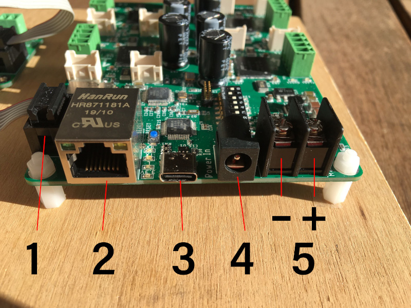
Number |
Description |
|---|---|
1 |
Electromagnetic brake terminal (STEP400) |
2 |
Ethernet Port |
3 |
USB-C Port |
4 |
(Primary Power Input) DC Barrel Plug |
5 |
(Primary Power Input) Screw Terminal |
Warning
Again, do NOT connect both 4 and 5. This will damage your controller.
As stated above, both devices have different power ratings and different ratings for each primary input.
Controller |
Board Max Power Rating |
Barrel Jack |
Screw Terminal |
|---|---|---|---|
STEP400 |
12V-76V @ 20A |
24V @ 5A |
76V @ 20A |
STEP800 |
9V-36V @ 16A |
24V @ 5A |
36V @ 16A |
The amps listed here reflect the cumulative maximum phase current draw of all motors, not the maximum current capacity of the power supply. Look at Current Capacity for more information. The STEP800 has a maximum phase current draw of 2A per motor whereas the STEP400 has a maximum of 5A. Please keep these limits in mind when choosing your motor.
DC Barrel Plug
The DC barrel has the following specifications beyond its power rating:
5.5mm outer diameter
2.1mm inner diameter
Center positive
Screw Terminal
The screw terminal has the following specifications beyond its power rating:
Negative left side, positive right side
M3 screw diameter
Use a wire terminal like the
NICHIFU TMEX1.25-3Nfor a more secure connection
Power Supply & Stepper Motor Ratings
Current vs Voltage
The copper windings inside a stepper motor behave as an inductor. When power is supplied to the inductor, current rises gradually–it is not instant. Stepper motors that operate through the ON/OFF cycle see decreased current the faster they move because the current cannot reach its maximum. Because the motor’s torque is virtually proportional to it’s phase current, that means higher speeds means lower torque.
Overcoming the Tradeoff
To overcome this tradeoff, you need to use a power supply with a high voltage rating. Remember, both boards have their maximum voltages, so keep that in mind when choosing a supply. To better articulate this point, see the following graph and note the correlation between a higher voltage providing higher current (aka torque) and a higher maximum speed.
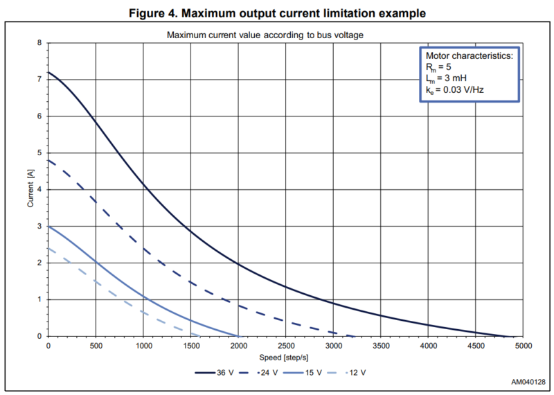
The required voltage varies greatly depending on the motor’s rating, required speed, and required torque. But, in general, the required voltage is roughly as follows:
NEMA17 and under: 24V
NEMA23 and bigger: 48V (or 72V for high speed)
This means the STEP800 may not be suitable for driving larger motors; however, some motors may produce high torque in a small form factor and vice versa with a large form factor. It’s imperative you review your motor’s voltage and current ratings.
The STEP400 does work with a minimum of 12V; however, since that is its on-board DC-DC converter’s minimum required voltage, there may be cases where the STEP400 resets on a slight voltage drop. This is especially the case during a motor’s inrush current, therefore we do not recommend a 12V power supply unless if you are driving a small motor at a low load.
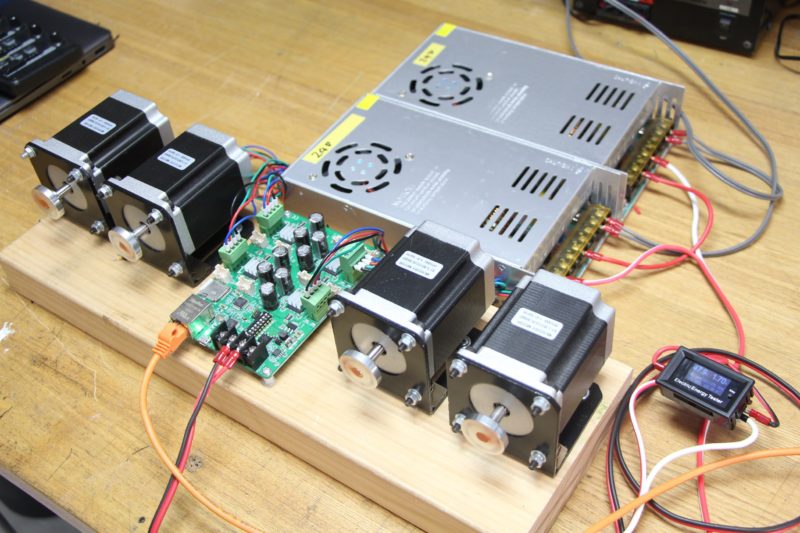
A STEP400 being supplied 48V through two 24V power supplies in series.
Current Capacity
The current capacity of the power supply is as equally important as its voltage. If a motor stalls it may draw a high amount of current that may exceed the capacity of the power supply. This will cause the overload protection circuit on the supply to trigger (if there is one) forcing the supply to shut down. Typically, you will likely need to only supply a few amps to drive small motors at low speeds. But large motors at high speeds often do require high voltage with high current (especially if they are under load). Depending on the quantity of motors, their usecases, as well as your circuit protection settings, we recommend a supply with at least 10A-20A capacity.
Networking
Configuration Tool
Both devices do have a microSD card slot included on the board. Using this slot, you can just about completely configure the device using our convenient Configuration Tool. This tool is a webpage, that can be accessed through your browser–so no third party software is required.
This tutorial uses default settings, so we will not be using the microSD card. Just leave the slot empty.
Note
If you are connecting the board through a network switch that is connected to an existing VLAN, you may need to use the configuration tool to pre-configure the device’s network settings and override those that will be set by the DIP switches as described below.
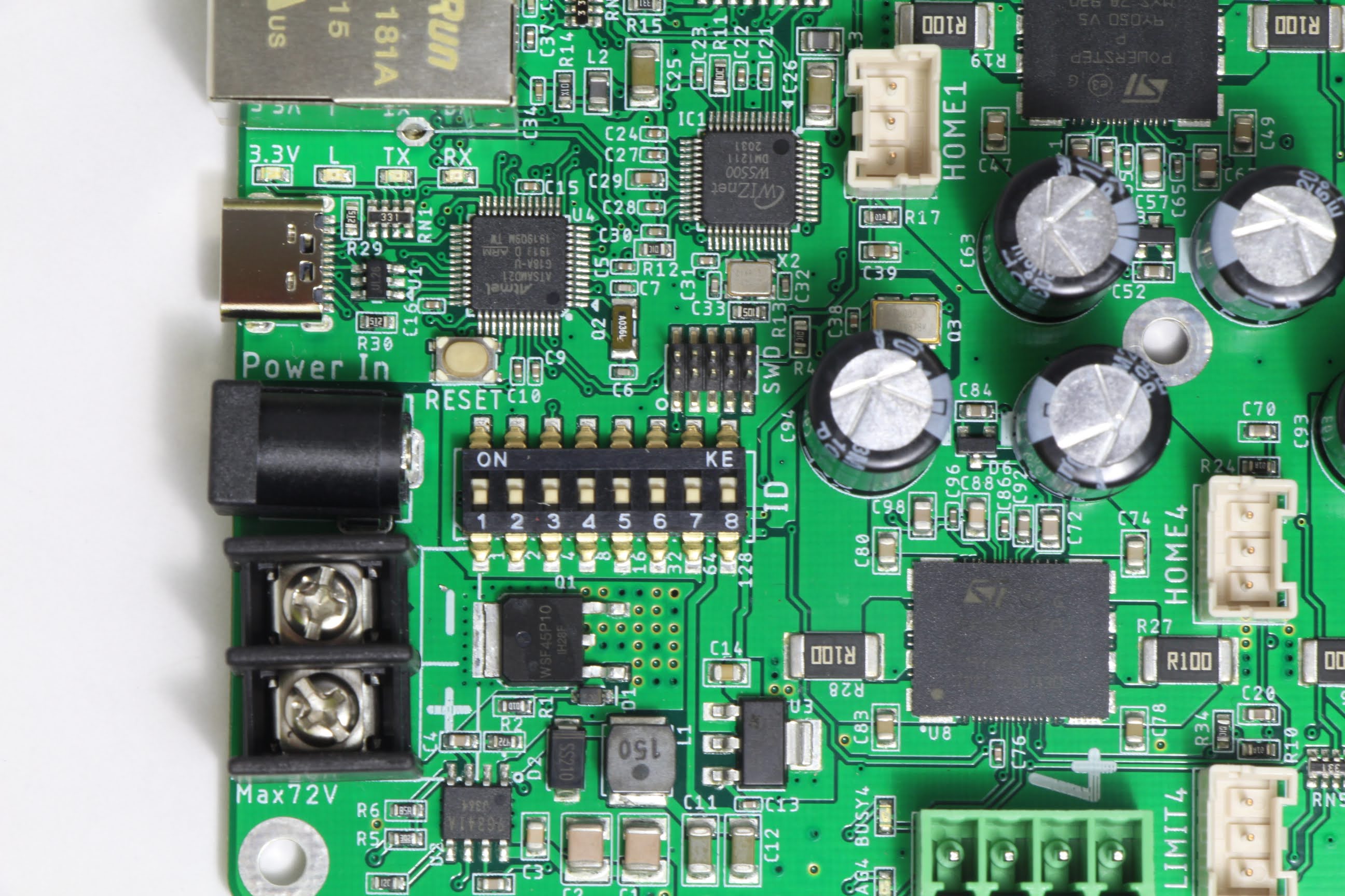
Dip Switches
The DIP switches on the board must be set to 1. This means only the left-most switch is ON and the rest are OFF. With this configuration, the board has the following network settings:
Name |
Value |
Description |
|---|---|---|
IP Address |
10.0.0.101 |
The IP address of the device |
Server Address |
10.0.0.10 |
The IP address of the server (i.e. your PC) |
Local Port |
50000 |
The port the device is listening on |
Server Port |
50101 |
The port on the server that the server is listening on |
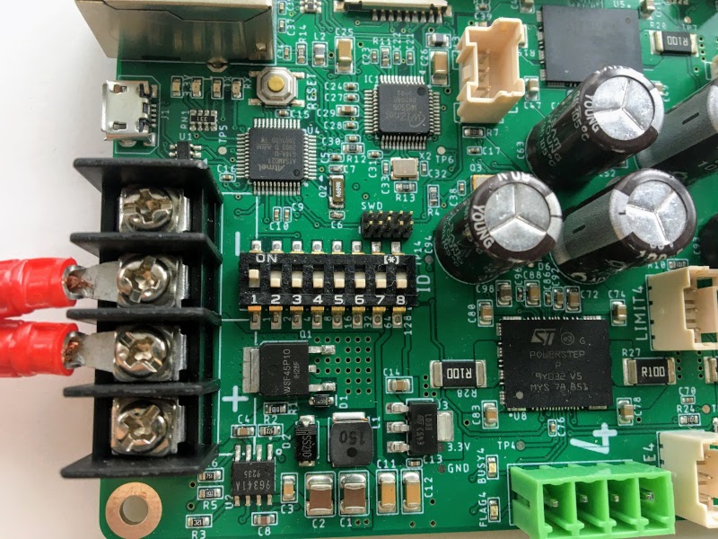
Configured DIP switches on the STEP400.
Now with the motor, power supply, and ethernet cord connected; and the DIP switches set, you may now power-on the device. Please remember the bottom side of the board does have high-voltage and high-current pins, so either place the board on non-conductive material or attach spacers to avoid damaging the board or hurting yourself.
PC Configuration
As seen in the table above, the device will expect your PC (server) to exist at a certain IP address. If you need to, you can set it statically by reviewing the guides linked below:
Name |
Value |
|---|---|
IP Address |
10.0.0.10 |
Subnet Mask |
255.255.255.0 |
DNS |
<Leave Empty> |
Default Gateway |
<Leave Empty> |
Running Basic Commands
Verifying the Connection
After configuring the above settings, you can verify your connection by running ping 10.0.0.101
from your terminal (Command Prompt on Windows).
From this point forward, how you send commands to the device will completely depend on if you’re
using python-step-series or one of the programs listed in Example Files. This tutorial
will describe each command and provide the code for python-step-series; however, it will be up
to you to determine how to send the commands through your program of choice.
Before sending configuration commands to the device, you must first send the command /setDestIp.
This tells the device where response messages will be sent. Until this command is received by the
device, it will not send any OSC messages beyond /booted. This is because operation may become
unstable if the device continues to send OSC messages to a non-existent destination. You will
receive the following response from the device if /setDestIp was received without issue:
/destIp octet1 octet2 octet3 octet4 isNewDestIp where octet<N> corresponds to each number
between the dots in your PC’s IP address and isNewDestIp will indicate if the dest ip has
changed (1) or not (0).
For python-step-series, the code may look like this:
from stepseries import commands
from stepseries.step400 import STEP400

device = STEP400(1, "10.0.0.101", 50000, "0.0.0.0", 50101)
device.on(None, lambda x: print(x))

device.set(commands.SetDestIP())

>>> DestIP(address="/destIp", destIp0="10", destIp1="0", destIp2="0", destIp3="10")
We are now ready to configure and control the device.
Get the Motor Running
Let’s send the command to run the motor at a desired speed: /run (int)motorID (float)speed.
motorID specifies which motor to run (1-4 on the STEP400, 1-8 on the STEP800). Each ID is
printed on the board for your convenience. Specifying 255 will indicate to run all motors at
your desired speed and is a valid parameter for almost every command requiring motorID.
speed specifies the speed and direction of the motor. The range you can set is from -15625.0 to
15625.0 steps/second. If you’re using a motor with 200 steps per revolution, specifying 200.0
will run the motor at 1 revolution per second (RPS). Negative values will run the motor backwards.
For example, to run an SM-42BYG011-25 at 1 RPS, the command /run 1 200 can be sent.
# For python-step-series
device.set(commands.Run(1, 200))
Is the motor now slowly spinning? If there is an issue, or you would like to stop it, set the speed
to 0 using the /run command or send /hardHiZ 255:
# For python-step-series
device.set(commands.HardHiZ(255))
Warning
Do not disconnect the motor while it is active and running. This will damage your board.
If everything succeeded, then congratulations! You’ve successfully ran your first motor. But, you
may have noticed the motor ran a little rough–lots of vibration and possibly noisy. This is where
KVAL and TVAL come in.
Setting KVAL
In most cases, the reason for rough operation of a motor is insufficient, or excessive, drive voltage. The KVAL register sets this voltage on a scale of 0-255 where 0 means no voltage (cannot move) and 255 is the same as your supply voltage. So, if you have a 24V supply, the motor will run on 24V at 255, or 12V for 128, and so-on.
Each parameter in the /setKVAL command has a unique function.
Name |
Description |
Initial Value |
|---|---|---|
holdKVAL |
Holding KVAL |
0 |
runKVAL |
Constant speed KVAL |
16 |
accKVAL |
Acceleration KVAL |
16 |
decKVAL |
Deceleration KVAL |
16 |
Let’s adjust these values while the motor is running. Send the command /run 1 200.
# For python-step-series
device.set(commands.Run(1, 200))
You can set individual KVAL parameters using commands like /setRunKval, but we are going to set
all 4 parameters at once. Let’s set holdKVAL to 0 and then gradually increase each of the
other three simultaneously. To do this, send the command /setKval 1 0 24 24 24. The syntax of
the command is /setKval (int)motorID (int)holdKVAL (int)runKVAL (int)accKVAL (int)decKVAL.
# For python-step-series
device.set(commands.SetKval(1, 0, 24, 24, 24))
This message specifies the first motor’s holdKval as 0 and the rest at 24 (approximately 9% of
your power supply voltage). Gradually increase the values until the motor begins to turn quietly.
For example: /setKval 1 0 32 32 32, then /setKval 1 0 40 40 40, etc.
# For python-step-series
device.set(commands.SetKval(1, 0, 32, 32, 32))

# then
device.set(commands.SetKval(1, 0, 40, 40, 40))

# etc...
As you increase each parameter, the motor’s torque will also increase; however, the motor will also begin to vibrate more and produce more heat. Be sure to set the parameters appropriately for your load.
Tip
Remember: we’ve already calculated configuration files for a variety of motors for you if you would like to use them.
Other Connections and Settings
Sensors and Switches
Each axis of the STEP400 and STEP800 has a HOME connector which allows for you to plug-in some
form of limit switch or equivalent sensor. Additionally, the STEP400 has LIMIT inputs for each
axis in addition to the HOME inputs.
HOME
Since the stepper motor cannot track its own position, a dedicated sensor is required to return to the home position on boot-up. It is directly connected to the motor driver IC and can be used for position management. The pin is pulled up to 3v3 (3.3V) inside the driver IC.
LIMIT
STEP400 Only
As stated above, the STEP400 has an additional LIMIT switch input that can be used to limit the
operational range of each motor. You can configure these inputs to halt the motor, or to be used as
another input for another purpose. Like the HOME input, this input is also pulled up to 3v3.
Connection Terminals
We use the XA series connectors from JST (J.S.T.MFG.CO., LTD.). For compatible connectors, please refer to the following:
Name |
Model Number |
Description |
|---|---|---|
(Reference) PCB Post |
B03B-XASK-1 (LF)(SN) |
Female connector on the PCB |
Housing |
XAP-03V-1 |
Male plastic housing |
Contact |
BXA-001T-P0.6 |
Crimp contact inserted into the housing |
Tip
We also sell pre-crimped sensor cables for your convenience. These are available here: https://ponoor.com/en/products/sensor-cable/
Pin Assignments
The pin assignments for both inputs are the same. The order of these pins are relative to how you are looking at your board. We assume you are viewing the board with the board’s name at the bottom and the power/ethernet ports at the top. This table is for the left-side ports; the right-side ports will be inverted as they are upside-down.
Pin (left-to-right) |
Function |
|---|---|
1 |
5V Output |
2 |
3v3 (Switch Input) |
3 |
GND |
Tip
They are also printed on the bottom of the boards for your convenience.
The driver responds when the input falls from HIGH (3v3) to LOW (0V). Therefore, the switch
must behave as “normally open”.
Network and DIP Switch
Dip Switch Settings
The DIP switch specifies the ID that is used to reply to OSC messages and is also reflected in the local IP address and expected server port number. The ID is set in binary with more information provided by Soundhouse’s Documentation.
Network Settings
Initial Settings
Item |
Initial Value |
|---|---|
IP Address |
10.0.0.100+ID |
MAC Address |
0x60, 0x95, 0xCE, 0x10, 0x02, 0x00+ID |
Server IP Address |
10.0.0.10 |
Local Port |
50000 |
Expected Server Port |
50100+ID |
IP Address and Expected Server Port
In its initial state, an ID will be added to IP address’s final octet and the expected server port. With this mechanism, you are able to operate multiple devices with the same firmware and settings file. On the server, if you are able to retrieve the IP address of the device, you can configure the device to not add its ID to the expected server port.
This feature can be disabled via the microSD card configuration.
MAC Address
A unique MAC address is assigned to the device; however, its initial value is set as seen in the table above. The unique MAC address is printed on the sticker on the bottom of the device beneath another sticker that should contain the device’s serial number. To use the assigned MAC address, please generate the settings file from the Configuration Tool and load it onto the microSD card.
Tip
A variety of settings can be preconfigured on the microSD card. See microSD Card Setup.
Functionality Descriptions
This section delves deeper into what the different functionalities offered by both boards are and what they do. Please refer to the Command Reference for what commands to send to control these different functionalities.
Voltage vs. Current Mode
There are two types of stepping control methods: constant voltage control (voltage mode) and constant current control (current mode). Only the STEP400 can switch between both voltage and current modes. The difference between these modes is well-explained in this presentation PDF by STMicroelectronics.
The differences can be described as follows:
Voltage mode is quiet and smooth, but is limited to lower speeds
Current mode is noisy, but can reach higher speeds
To better illustrate this point, here is a demonstration video to show the differences between these two modes.
First, the motor runs under constant voltage mode. After around 800 steps/sec, the motor cannot run properly and starts to vibrate and stalls at about 1,400 steps/sec. Overall, the motor runs quietly until the vibration starts. A microphone is attached to the motor so that we can capture the smallest noises.
Next, the motor is switched to constant current mode. It is noisy, but can drive to a higher speed. In this mode, we were able to achieve more than 11,000 steps/sec before the motor started to vibrate and stall.
KVAL and TVAL
KVAL register values are applied to control the drive voltage in voltage mode; likewise, TVAL registers are used to control the drive current in current mode. Both act as percentage multipliers to dictate what percentage of the power supply voltage or current is sent to the motors. Although they are the same registers internally in the driver, our firmware keeps them separated and rewrites them when the modes are changed.
Notes on Voltage Mode
In voltage mode, KVAL is used to set what percentage of the power supply voltage should be applied to the motor. If a high voltage power source is used, excessive current may flow when the motor is spinning at lower speeds. To compensate this current imbalance, there is a group of registers to lower the supplied drive voltage at low speeds and supply higher voltages at higher speeds. The calculation of these register values is described in STMicroelectronic’s application notes. In the STEP400, these registers can be set with /setBemfParam command or with the Config Tool.
Additionally, we have calculated the register values for some motors based on our actual measurements and have made them available as configuration files. We have only a small numbers of configuration files at the moment, but we are planning to add more in the future. If you have a motor that is not listed in the example files and have determined these configurations on your own, we would deeply appreciate you sharing your configurations with us and the community.
Notes on Current Mode
In current mode, which is only available on the STEP400, TVAL registers are used to set the target current value. The current can be set up to 5A in increments of 78mA on the STEP400. You’ll need a high voltage power supply to deliver the target current when the motor is running at high speed. Although the powerSTEP01’s actual current drive capability is 10A, the STEP400 has the upper rating limit of 5A due to the power rating limitation of the current sensing resistor. At 5A phase current, the torque is considerably strong, and the tiniest mistake may lead to great physical danger. In such situations we recommend to use use an industrial grade motor driver.
Switching Between the Modes
Use the following commands to switch between the modes:
/setVoltageMode - switch to voltage mode
/setCurrentMode - switch to current mode
The motor must be in the high impedance (High Z) state before switching the mode. For example, if you are going to switch the Motor 1 to current mode, send these commands in the following order:
/hardHiZ 1/setCurrentMode 1
Microstepping is limited to a minimum of 1/16 in current mode. Any lower value than 1/16 will be regarded as 1/16. When you change microstep value, the coordinate system will also change. For example, for one full shaft rotation of a 200 step motor in 1/128 microstepping mode, 200x128=25600 steps are made; but one rotation in 1/16 microstepping mode is 200x16=3200 steps.
Speed Profile
Overview
Speed profile sets the acceleration (acc), deceleration (dec), and maximum speed (maxSpeed) values of the motor prior to the motor moving. These values depend on the following:
Motor Specifications
Power supply voltage
Load
Voltage mode or current mode
While we provide some example defaults, you need to set these values according to your actual environment. This requires some trial and error on your part.
Setting the Profile
Use /setSpeedProfile to set the above three values. Acc and dec cannot be set unless the motor is stopped; however, maxSpeed can be set at any time.
You can also set the minimum speed (minSpeed) with /setMinSpeed.
It is unlikely to be used for any actual application, but this speed
will be used for /releaseSw speed as a part of the homing procedure.
Types of Motor Operation
Constant Speed
The /run command is used to drive the motor at a constant speed. The
acceleration, deceleration, and maximum speed curves set by
/setSpeedProfile are adhered to by this command. The motor runs
perpetually until speed 0 (/run 0) or a stop command is sent. The
motor will not run faster than the maximum speed set in the speed
profile. Sending a speed to run faster than this profile setting will
cause the motor’s speed to be truncated to that setting. The motor will
be kept in the BUSY state during the acceleration and deceleration.
/goUntil and /releaseSw are also considered constant speed commands.
Positioning
The trapezoidal drive towards the specified position is performed according to the speed profile. In other words, it accelerates according to the acceleration rate of the speed profile, then drives at constant speed when it reaches the maximum speed, and then decelerates at specified deceleration rate at the timing calculated backwards to stop at the specified position. It may start decelerating before it reaches the maximum speed, especially when you want to accelerate / decelerate at a relatively slow rate. It remains in the BUSY state until the motor stops. It’s not possible to interrupt the current positioning motion with another positioning motion.
Typical commands for positioning operation are /goTo and /move.
Other commands include /goHome, /goMark, and /goToDir.
NOTE: With STEP-series Universal Firmware, positioning motions (except /move) can interrupt another positioning motions.
Servo Mode
This is not a function of the motor driver, but a mode of driving implemented in the firmware. It constantly updates the constant speed operation to follow a given target position. This mode is similar to a radio controlled servo motor. No other motor motion commands can be sent while the motor is operating in this mode.
Types of Stops
There are two options with a total of four different commands, as follows:
Decelerating according to the speed profile or stop instantly
Keeping magnetized/excited or entering a high impedance (High Z) state after stopping
State after stop |
Deceleration stop |
Immediate stop |
|---|---|---|
Excited |
SoftStop |
HardStop |
HiZ |
SoftHiZ |
HardHiZ |
The excited state is the state in which voltage or current (torque) is
maintained to hold the motor’s position according to KVAL_HOLD or
TVAL_HOLD, respectively. The high impedance (HiZ) state is when
the current is cut off and no holding torque is maintained. Any loads
the motor is moving may fall or lose their positioning during HiZ.
Homing
When the system powers up, it doesn’t know where the motor is currently positioned. It could be pointing to various directions depending on the timing of the last time the system was shut off.
Also, if the stepper motor receives exceeding external force, the step will slip out of alignment (stall). If this happens, the motor will continue to work with an unknown offset between the expected position and its actual.
Therefore, applications that have position or orientation must use sensors to detect a reference position on startup or periodically while it is active. This action is called homing.
Switches and Sensors
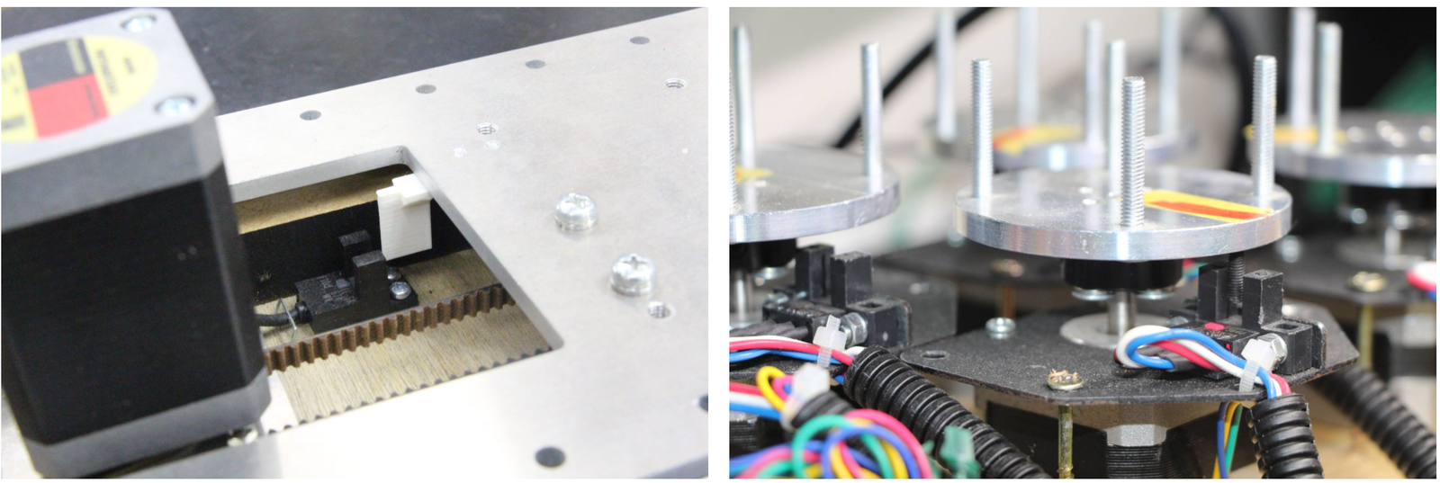
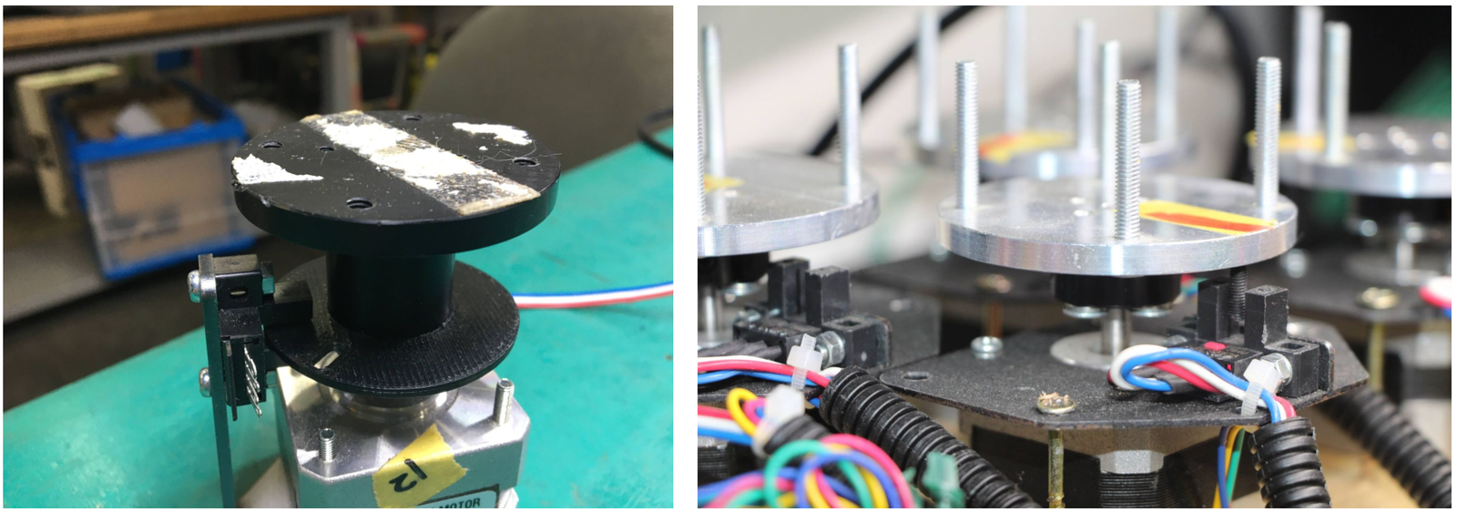
Two different configurations of a homing sensor
Photointerrupters are often used as home sensors. On the left, a white piece of plastic attached to the slider blocks the photointerrupter’s light-emitting and receiving parts. The right side is an example of a rotary table where the photo interrupter responds to the black screw.
Other devices such as microswitches or photoelectric sensors are also used for the sensing.
To make interfacing with these sensors and switches from the controller, we provide pre-made connection cables (scroll all the way down to the bottom of the page when you click “BUY”).
HOME and LIMIT Sensors
Each axis of both the STEP400 and STEP800 has a HOME connector which can connect sensors or switches. The STEP400 has LIMIT sensor inputs in addition to HOME inputs. 5V is supplied to each connector for the sensing power source.
HOME
This input is connected directly to the motor driver chip and can be used in conjunction with the driver’s homing function. Usually, this connector is used for the home sensor.
LIMIT (STEP400 Only)
Some applications may require two sensors. For example, a slider has a limited operating range and if it stalls during operation, it may collide with one of either end. In such cases, installing sensors on both ends of the slider will prevent collisions.
The motor can be set to force-stop when these sensors respond, but these can also be used as simple switch inputs separated from the motor operation. For example, you can connect a push button to one of them and press to send an OSC message.
Collision Prevention Settings
You can limit the motor’s rotate direction when the HOME or LIMIT
sensors are activated. With the commands /setProhibitMotionOnHomeSw
and /setProhibitMotionOnLimitSw, you can prohibit the actuator from
moving towards homingDirection when the HOME sensor is active, or
the reverse direction towards homingDirection when the LIMIT sensor
is active. With this, you can prevent the mechanism from colliding with
its bounds.
homingDirection can be set with /setHomingDirection or
with the Config Tool. This setting is also used for the /homing
command.
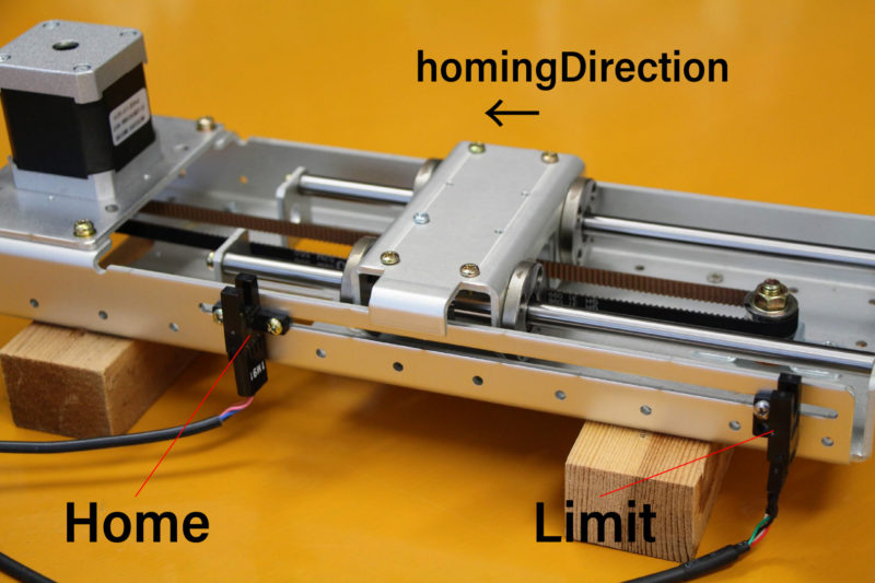
Homing Direction
Homing Commands
The homing command is /homing. This command consists
of two commands, /goUntil and /releaseSw, which are inherited
from the powerSTEP01/L6470 motor driver chip. Let’s look closer at those
commands.
/goUntil
First, use this command to move towards the home sensor. The motor will decelerate and then stop when the home sensor activates (if it has been set up as such).
/releaseSw
This command slowly moves the motor in the opposite direction from the
current position and stops immediately when the HOME sensor reading is
no longer active. The position where the motor stops is the origin/home
position! However, strictly speaking, the /goUntil command does not
stop immediately, but stop after deceleration. Its current position has
a slight negative offset from the point where the sensor actually
responded. This is not accounted for in the firmware as every
environment is different.
Both commands can be configured to reset the current position to zero the moment the sensor responds with /setHomeSwMode.
To better illustrate this interaction, here is a demo video.
/homing
It is possible to send above two commands over OSC one after another,
however, the /homing command executes this sequence in single
operation. It will automatically complete the home sequence according to
the homing direction and homing speed which are pre-configured with the
Config Tool or with the commands /setHomingDirection and
/setHomingSpeed, respectively.
Homing Timeouts
Both /goUntil and /releaseSw have pre-configured timeouts. When
either command times out–that is, the HOME sensor’s state has not
changed after a period of time–the controller will halt the movement of
the motor. This is to prevent the moving part from being pushed against
other mechanical objects endlessly and for safety.
Normally Open and Normally Closed
Electrical Connections
Let’s explore “sensor reaction” a little bit more in detail. The pin assignments of HOME and LIMIT connectors are as follows.
Pin number |
Function |
|---|---|
1 |
GND |
2 |
Switch/Sensor input |
3 |
5V Power Output |
Each sensor pin (2) on HOME and LIMIT is pulled up to 3.3V. To connect the switch, connect the GND (1) and the sensor terminal (2). When the switch is pressed, it is connected to the GND pin and the voltage drops from 3.3V to 0V. When the voltage changes from HIGH level to LOW level (a.k.a. Falling Edge), the sensor is considered to have activated.
Let’s take photo interrupter EE-SX671A as an example, where the connection is as follows:
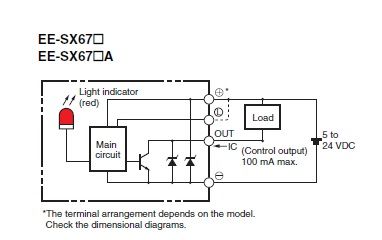
EE-SX671A Diagram
Pin number |
Function |
Sensor pin |
|---|---|---|
1 |
GND |
|
2 |
Switch/Sensor input |
OUT |
3 |
5V Power Output |
Light or No Light Activation
This is the part you need to consider carefully before ordering a sensor.
Dark activated or light activated
In the case of the left picture, the light enters into the sensor at the home position, but in the picture on the right, the light is blocked at the home position.
There are two types of sensors, one that turns on when light enters and one that turns on when light is interrupted. In the case of the above Omron sensor, the action is toggled by connecting the “L” and “+”” terminals.
The mechanism and sensor must be combined in such a way that the sensor pin goes from HIGH to LOW at the home position.
Rotary Tables
In the left example on the picture above, the response position of the home sensor will differ between clockwise and counterclockwise, depending on the size of the hole. The controller can notify both HIGH to LOW and LOW to HIGH changes of the home sensor by OSC messages. The message also includes the rotation direction, so you can align the home position if you write a conditional sequence for each rotation direction. This reporting can be configured with /enableHomeSwReport.
Servo Mode Explained
As stated above, servo mode is not a function native to the motor driver chip on the board. While seemingly similar to positional commands, servo mode commands allow you to define a new target position while the motor is moving. This is not possible with positional commands which require the position to be set in advance of the motor’s movements. New positional targets are not updated until after the current target is reached. While this mode is active, other functional commands cannot be sent.
Example Behavior of Servo Mode
Initializing Steps for Servo Mode
Toggling the Mode
The command /enableServoMode enables or disables Servo Mode. Upon starting Servo Mode, the driver must not be in the BUSY state.
Updating the Target Position
The target position can be updated by the /setTargetPosition command. When the Arduino Sketch receives a new target position, it will compare the new position with the current one and change the rotation speed of the motor. Additionally, you can send target positions to all four motors at the same time with /setTargetPositionList.
Types of Control Parameters
The motor’s rotation speed is calculated by a technique called “PID Control”. To better illustrate the purpose of PID, refer to the following graph:
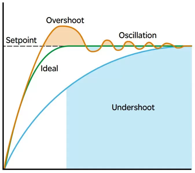
Please refer to this graph when the control parameters are discussed below. These parameters can be set with the command /setServoParam.
Proportional Gain (kP)
PID control uses differences of current position and target position (deviation) for the control. That is, it approaches the target position by rotating faster when the deviation is large, and rotates slower when the deviation is small. The proportional gain defines how much influence to the speed will be given from the deviation. If the value is too small, it will take time to approach the target position, and if the value is too large, an “overshoot” may occur in which case the target position is passed.
Integral Gain (kI)
If there is only the proportional control, the rotation speed will get slower and takes very long time to compensate the offset when approaching to the target position. In this case, adding the time integral of the deviation to the control value will effectively compensate the offset. By applying large integral gain, you could compensate the offset quickly; however, it may cause the overshoot, or even the continuous oscillation by trying to compensate the overshoot.
Differential Gain (kD)
In case an overshoot or oscillation related errors occurs, this parameter is used to eliminate steep changes in deviation–that is to say, it acts like a damper that continually decreases each oscillation.
Methods for Determining PID Parameters
Step by Step Procedures
PID Control Parameters must be determined from the actual acceleration, deceleration, and the maximum rotation speed (speed profile). Determine the control parameters by following these steps:
Decide the KVAL (in case of current mode, TVAL) that is matched to the rated value and load.
Decide the operational acceleration, deceleration, and the maximum rotation speed (speed profile).
Adjust the PID control gains.
The Decisions of PID Control Gain
There are multiple methods for deciding the optimal PID Control Gain. However, it may also depend on the factors like the objective of movement, or the frequency of target position change. Therefore we determine the values by steps described as follows and do trial and error on the actual set up.
1. kP
Set all kP, kI, kD, to 0.0 and gradually raise the kP until the motor starts to oscillate around its target position. When the target position changes only sometimes, we often set only kP while keeping other kI and kD values at 0.0.
2. kI
In case when the target position only changing once every couple of seconds, you set the movement to quick and responsive by raising the kI value. Yet for example, when the target position is sent at 60fps, the acceleration towards the each new target position would cause the vibration and loose smooth transition. Depending on the priority of the quickly response to the target position or smooth movement for the whole operation, the preferable values may change.
3. kD
We gradually raise the kD if oscillation or overshoot is observed when approaching the target.
Technical Information
Advanced information regarding firmware and the actual hardware around the boards is contained here. A basic understanding of programming Arduinos and the Arduino IDE or PlatformIO with VSCode is assumed.
Firmware
Because the main control unit (MCU) is an Arduino Zero, the firmware is actually an Arduino sketch. This means uploading the firmware is done using the Arduino IDE or PlatformIO in VSCode.
The latest firware version can be viewed at this GitHub Releases page. The code itself lives in this GitHub Repository where it can be downloaded for use throughout this module.
Checking the Version
Two methods exist to check the current version of the firmware:
Using the OSC command
/getVersionConnecting a USB cable to the board and typing
sin the Serial Monitor
Method 1: OSC Command
This method only requires you to send the /getVersion command to the
board. The resulting response will tell you the current version of the
firmware.
For example:
/version "STEP800_R1_UNIVERSAL 1.0.1 Mar 24 2022 11:17:29"
Method 2: Over USB
Connect the USB-C cable to the board and to your PC. Then open Serial
Monitor in the IDE you’re using. Send the command s and you should
receive a response containing the version.
For example:
-------------- Firmware --------------
Firmware name : STEP800_R1_UNIVERSAL
Firmware version : 1.0.1
Compile date : Mar 24 2022, 11:17:29
Uploading New Versions
Compiling with PlatformIO
The firmware is primarily developed using PlatformIO. Each repository has a dedicated directory you can open using the “Open Project” menu of PlatformIO. All dependencies are automatically installed when you compile the project for the first-time.
Compiling with Arduino
Using the Arduino IDE requires a bit of manual setup than PlatformIO. To begin, the Arduino Zero board must be first installed in the IDE using the Board Manager. This Quickstart Page is a great resource for how to do this procedure.
Next, the following libraries need to be installed. Here’s a page describing how to install libraries.
STEP400 only: Ponoor PowerSTEP01 Library
STEP800 only: Ponoor L6470 Library
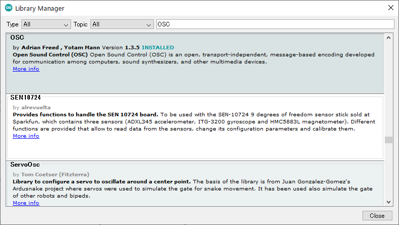
Note
There many OSC libraries that may be listed in the Library Manager. This project uses the library made by CNMAT and is listed as OSC. Note that the creators are listed as Adrian Freed and Yotam Mann, not CNMAT.
Compiling/Uploading the Sketch
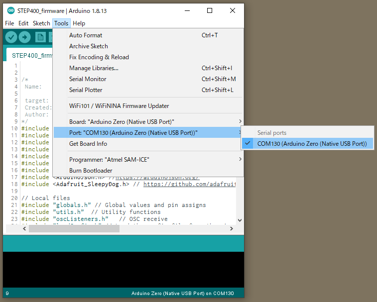
Before compiling, ensure the .ino file is open and the board
“Arduino Zero (Native USB Port)” in Tools > Boards is selected for
the Arduino IDE.
PlatformIO should already be configured for this project, so no action should be taken.
Now the firmware can be compiled and uploaded using either IDE.
Extra Notes
As a safety precaution, the electromagnetic brake should be disconnected from the board. While uploading the firmware, defaults are sometimes reset which may lead to the load being held by the brake to be dropped.
Connecting just the USB-C cable is not enough to power the motor driver chips on either board. So, while you can upload sketches and perform some basic commands on the board, no movement will be possible unless additional power is provided.
Occasionally, the Arduino Zero may fail to write. In case this happens, try double-clicking the RESET switch and putting the board in bootloader mode. Then try uploading again. In this mode, the sketch will not boot and the LED
Lwill begin to fade. You also have to reselect a different serial port.
Diagnosing via USB
Apart from uploading new firmware, the USB-C port on the device is also used to debug and monitor.
Note
The USB-C port only powers the Arduino portion of the device. If you wish to run any motors, be sure to also connect (only) one of the primary power inputs.
Note
If providing supplemental power, be sure to connect the USB-C cable last (or press RESET after doing so). Because the motor controllers will be in an unknown state if this process is flipped, you may encounter undefined behavior.
Serial Monitor
This portion of the tutorial assumes you’re using the Arduino IDE. Any serial port terminal client that can send and receive text strings can also be used.
Selecting the Port
Tools > Port > COMXXX (Arduino Zero (Native USB Port))
Open Serial Monitor
The Serial Monitor is what you use to communicate the with device. Opening this tool can be done in a few ways.
First way: Click the magnifying glass
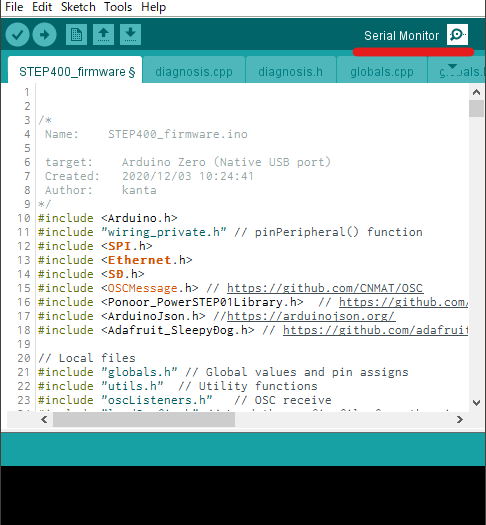
Second way: Tools > Serial Monitor
Third way: CTRL + SHIFT + M
Diagnosis Menu
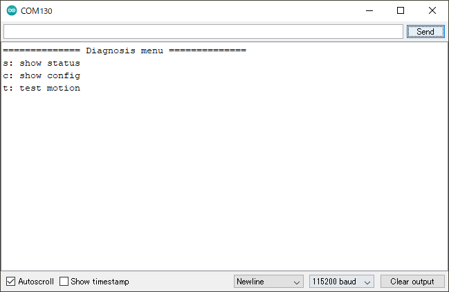
With the Serial Monitor now open, ensure that the baud rate is set to 115200. Changing the baud rate may cause the board to reset, so keep that in mind if a load is connected to your board–it may fall.
Next, type the letter m and press Enter or click Send. You should now see something like the following:
Status
Sending s allows you to retrieve it’s hardware status.
The first output block you will see is the firmware information on the MCU.
============== Current Status ==============
-------------- Firmware --------------
Firmware name : STEP400
Firmware version : 1.0.0
Compile date : Mar 19 2021, 10:27:55
Applicable config version : 1.0
Loaded config version : 1.0 [CONFIG_VERSION_APPLICABLE]
Loaded config version shows the config.txt version number read
from the microSD card. Depending on the version of the config and the
firmware, you’ll get one of the following messages:
Message |
Description |
|---|---|
CONFIG_VERSION_UNDEFINED |
Unknown config version |
CONFIG_VERSION_NOTLOADED |
The config could not be read from the microSD card |
CONFIG_VERSION_NOTLOADED |
The config version is old |
CONFIG_VERSION_APPLICABLE |
The config and firmware versions matched |
CONFIG_VERSION_NEW |
The config file’s version is newer than the firmware (the firmware is old) |
Next output is the DIP Switch.
-------------- DIP Switch --------------
BIN : 0000 0001
DEC : 1
BIN: The current positions of all switches on the board. Please note that on the board, the left-most position is the right-most position here in tool.DEC: The decimal representation of the switch.
Ethernet status is shown next.
-------------- Ethernet --------------
Ethernet hardware status: 3 -EthernetW5500
Ethernet link status: 2 -LinkOff
isDestIpSet : No
Ethernet hardare status: The status of the built-in ethernet controller. If everything is worker,EthernetW5500will be shown.EthernetNoHardwareindicates an issue is present.Ethernet link status: The status of the ethernet cable.LinkOnandLinkOffare self-explanatory. IfUnknownis present, that indicates an issue with the controller is likely present.isDestIpSet: Shows if/setDestIphas been recieved.
And finally, the status for the microSD card is shown.
-------------- microSD --------------
SD library initialize succeeded : Yes
SD config file open succeeded : Yes
SD config JSON parse succeeded : Yes
SD library initialize succeeded:Noif the card is not inserted.SD config file open succeeded: Shows ifconfig.txtwas successfully opened on the card.SD config JSON parse succeeded: Shows if the content ofconfig.txt(JSON) was read correctly.
We now move into status information for the motor driver chips.
STEP400 Only
-------------- Motor Driver --------------
PowerSTEP01 SPI connection established : Yes
PowerSTEP01 ID#1
    STATUS: 0xE603
    High impedance state : Yes
    BUSY : No
    Motor direction : Reverse
    Motor status : Stopped
    UVLO (Undervoltage lock out) : No
    Thermal status : Normal
    OCD (Overcurent detection) : No
    Stalled : No
    SW_F: 0 -HOME senser input open.
    ADC_OUT: 31 -LIMIT senser input open.
PowerSTEP01 ID#2
    ...
PowerSTEP01 ID#3
    ...
PowerSTEP01 ID#4
    ...
If communication with the PowerSTEP01 driver chips is unsuccessful
because the chips are unpowered, for example, PowerSTEP01 ID#<1-4>
will not be shown.
STEP800 Only
-------------- Motor Driver --------------
L6470 SPI connection established : Yes
L6470 ID#1
    STATUS: 0x7E03
    High impedance state : Yes
    BUSY : No
    Motor direction : Reverse
    Motor status : Stopped
    UVLO (Undervoltage lock out) : No
    Thermal status : Stopped
    OCD (Overcurent detection) : No
    Stalled : No
    SW_F: 0 -HOME senser input open.
L6470 ID#2
    ...
L6470 ID#3
    ...
L6470 ID#4
    ...
L6470 ID#5
    ...
L6470 ID#6
    ...
L6470 ID#7
    ...
L6470 ID#8
    ...
Like the STEP800 above, L6470 ID#<1-8> will only be shown if
connection to the driver chips was successful.
Next are the modes and electromagnetic brake and homing statuses.
-------------- Modes --------------
Servo Mode :  No, No, No, No
Current Mode :  No, No, No, No
Electromagnetic Brake Enable :  No, No, No, No
Brake status :
#1 : BRAKE_ENGAGED
#2 : BRAKE_ENGAGED
#3 : BRAKE_ENGAGED
#4 : BRAKE_ENGAGED
Homing status : 0, 0, 0, 0
Brake status |
Description |
|---|---|
BRAKE_ENGAGED |
Brake is engaged |
BRAKE_DISENGAGE_WAITING |
In transition to brake release |
BRAKE_DISENGAGED |
Brake released |
BRAKE_MOTORHIZ_WAITING |
In transition to brake engage |
ID |
Homing status |
Description |
|---|---|---|
0 |
HOMING_UNDEFINED |
Not homing yet |
1 |
HOMING_GOUNTIL |
Moving towards sensor |
2 |
HOMING_RELEASESW |
Leaving from sensor active area |
3 |
HOMING_COMPLETED |
Homing completed |
4 |
HOMING_TIMEOUT |
Time out was detected while homing |
Config
By entering the letter c, you are able to retrieve the current configurations of the board. Note that the output reflects the current settings on the device, not what is loaded on the microSD card if you have one inserted.
For example, the following output may shown if the STEP400 is booted without a microSD card:
============== Configurations ==============
-------------- Config file --------------
SD config file open succeeded : No
SD config file parse succeeded : No
configTargetProduct : ---
configName : Default
config version : -1.0 [CONFIG_VERSION_NOTLOADED]
-------------- Network --------------
My Ip : 10.0.0.101
isMyIpAddId : Yes
Dest Ip : 10.0.0.10
DNS : 10.0.0.1
Gateway : 10.0.0.1
Subnet mask : 255.255.255.0
MAC address : 60:95:CE:10:05:01
isMacAddId : Yes
inPort : 50000
outPort : 50101
isOutPortAddId : Yes
bootedMsgEnable : Yes
isDestIpSet : No
reportErrors : Yes
-------------- Report & Alarm --------------
reportBUSY :  No, No, No, No
reportBUSY :  No, No, No, No
reportHiZ :  No, No, No, No
reportHomeSwStatus :  No, No, No, No
reportLimitSwStatus :  No, No, No, No
reportDir :  No, No, No, No
reportMotorStatus :  No, No, No, No
reportSwEvn :  No, No, No, No
reportUVLO :  Yes, Yes, Yes, Yes
reportThermalStatus :  Yes, Yes, Yes, Yes
reportOCD :  Yes, Yes, Yes, Yes
reportStall :  Yes, Yes, Yes, Yes
reportOCD :  Yes, Yes, Yes, Yes
OCThreshold : 15, 15, 15, 15
-------------- driverSettings --------------
homingAtStartup :  No, No, No, No
homingDirection(1:FWD,0:REV) : 0, 0, 0, 0
homingSpeed : 50.00, 50.00, 50.00, 50.00
homeSwMode : 1, 1, 1, 1
prohibitMotionOnHomeSw :  No, No, No, No
limitSwMode : 1, 1, 1, 1
prohibitMotionOnLimitSw :  No, No, No, No
goUntilTimeout : 10000, 10000, 10000, 10000
releaseSwTimeout : 10000, 10000, 10000, 10000
microStepMode : 7, 7, 7, 7
isCurrentMode :  No, No, No, No
slewRate : 5, 5, 5, 5
electromagnetBrakeEnable :  No, No, No, No
brakeTransitionDuration : 100, 100, 100, 100
-------------- speedProfile --------------
acc : 1000.00, 1000.00, 1000.00, 1000.00
dec : 1000.00, 1000.00, 1000.00, 1000.00
maxSpeed : 650.00, 650.00, 650.00, 650.00
fullStepSpeed : 15610.00, 15610.00, 15610.00, 15610.00
-------------- Voltage mode --------------
kvalHold : 0, 0, 0, 0
kvalRun : 16, 16, 16, 16
kvalAcc : 16, 16, 16, 16
kvalDec : 16, 16, 16, 16
intersectSpeed : 1032, 1032, 1032, 1032
startSlope : 25, 25, 25, 25
accFinalSlope : 41, 41, 41, 41
decFinalSlope : 41, 41, 41, 41
stallThreshold : 31, 31, 31, 31
lowSpeedOptimize : 20.00, 20.00, 20.00, 20.00
-------------- Current mode --------------
tvalHold : 0, 0, 0, 0
tvalRun : 16, 16, 16, 16
tvalAcc : 16, 16, 16, 16
tvalDec : 16, 16, 16, 16
fastDecaySetting : 25, 25, 25, 25
minOnTime : 41, 41, 41, 41
minOffTime : 41, 41, 41, 41
-------------- Servo mode --------------
kP : 0.06, 0.06, 0.06, 0.06
kI : 0.00, 0.00, 0.00, 0.00
kD : 0.00, 0.00, 0.00, 0.00
Test Motion
Motors can also be tested via the Serial Monitor by entering the letter t. All motors will rotate 25600 steps, or one rotation at 200 steps with 1/128 microstepping enabled.
Hardware - STEP400
PCB Dimensions
120x84x1.6mm
There are five M3 mounting holes on all four corners and one included in the middle. The extraneous material at the top and bottom of the picture below is removed during production.
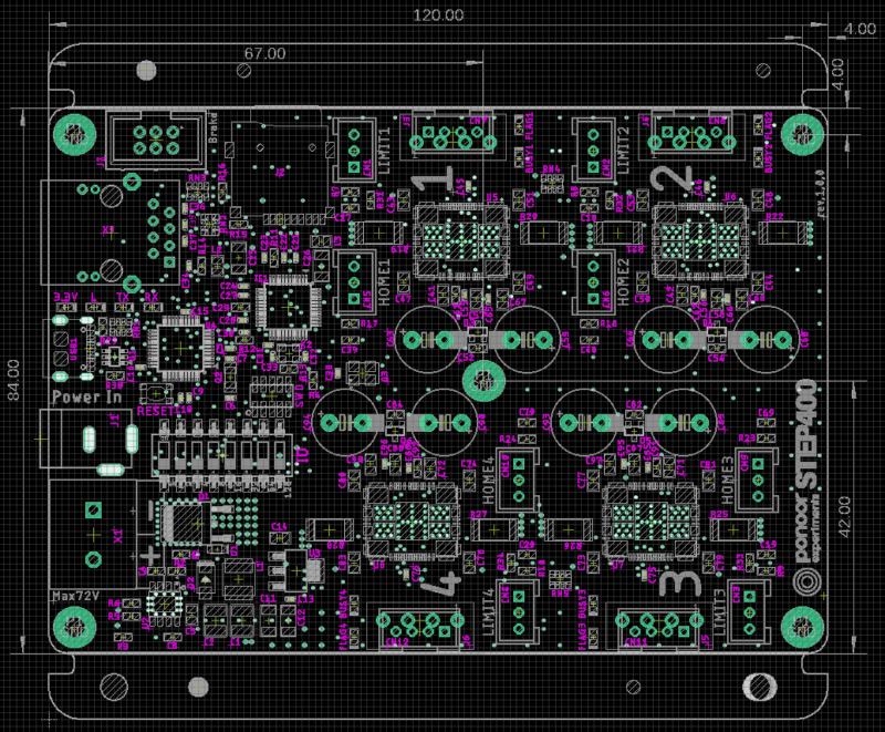
We also provide a PDF drawing of the board and it’s components for your convenience.
System
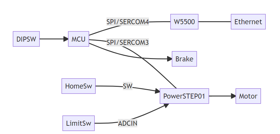
Like above, we also provide the wiring schematics of the board.
The primary components of the board are as follows:
Components |
Manufacturer |
Model number |
|---|---|---|
MCU |
Microchip |
|
Ethernet Controller |
Wiznet |
|
Stepper Driver |
STMicroelectronics |
|
DC-DC Converter |
ROHM |
Pin Assignments
Pin |
Function |
Notes |
|---|---|---|
D0 |
DIPSW8 |
|
D1 |
Brake4 |
|
D2 |
DIPSW5 |
|
D3 |
DIPSW7 |
|
D4 |
SD_CS |
|
D5 |
Brake3 |
|
D6 |
PowerSTEP01_MISO |
|
D7 |
DIPSW1 |
|
D8 |
Brake2 |
|
D9 |
DIPSW6 |
|
D10 |
W5500_CS |
|
D11 |
PowerSTEP01_MOSI |
|
D12 |
PowerSTEP01_SCK |
|
D13 |
L |
|
D20/SDA |
NC |
Pad on PCB |
D21/SCL |
NC |
Pad on PCB |
D22/MISO |
W5500_MISO |
|
D23/MOSI |
W5500_MOSI |
|
D24/SCK |
W5500_SCK |
|
D30 |
DIPSW2 |
|
D31 |
DIPSW4 |
|
D38 |
NC |
Pad on PCB |
A0 |
PowerSTEP01_CS |
|
A1 |
Brake1 |
|
A2 |
PowerSTEP01_RESET |
|
A3 |
W5500_RESET |
|
A4 |
SD_DETECT |
|
A5 |
DIPSW3 |
Note
Since the PowerSTEP01_RESET and W5500_RESET are
connected independently to their respective chip’s reset pins, be sure
to set pinMode to OUTPUT and set each of the state pins’ to
HIGH.
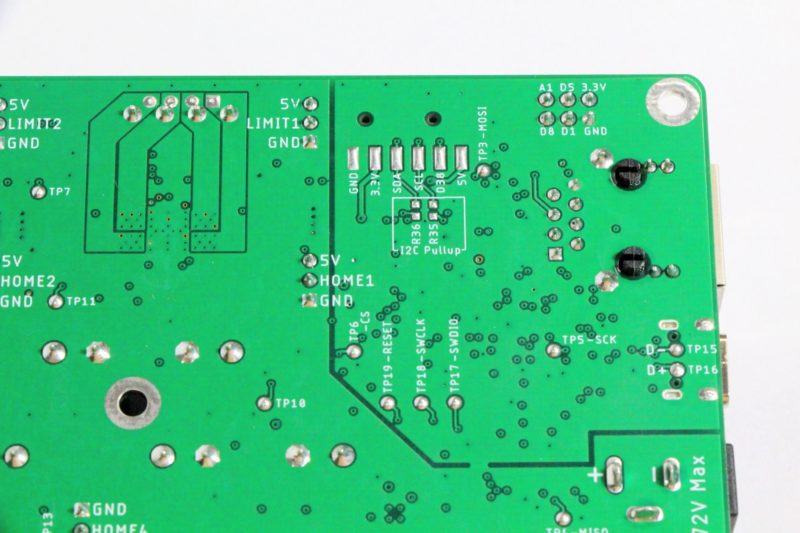
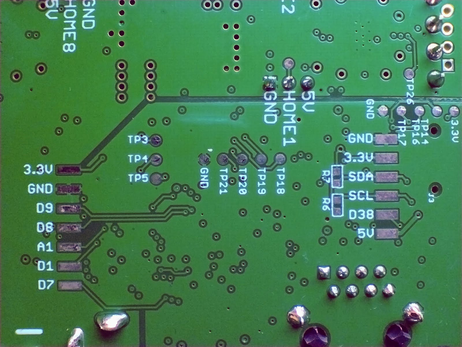
Pads on the PCB’s Rear Side
There are unassigned pins and power pads on the rear side of the PCB. They are 2.54mm pitch, so you can attach surface-mount pin headers and IC sockets. R35 and R36 can be used for the pull-up of the I2C data (SDA) and clock (SCL) pins. The chip size is 1608 (0603).
Since these pins are not implemented or controlled in the firmware we provide, it is on you to customize the firmware to implement the functionality you need.
SPI Assignment
The STEP400 uses different SPI ports for the PowerSTEP01 motor driver chips and the W5500 ethernet controller for easing control via the firmware. Here is a very informative guide about SPI allocation on the ATSAMD21.
W5500
Pin |
Function |
SERCOM |
SERCOM Alt |
|---|---|---|---|
D22/MISO |
MISO |
SERCOM4.0 |
|
D23/MOSI |
MOSI |
SERCOM4.2 |
|
D24/SCK |
SCK |
SERCOM4.3 |
PowerSTEP01
Pin |
Function |
SERCOM |
SERCOM Alt |
|---|---|---|---|
D6 |
MISO |
SERCOM3.2 |
|
D11 |
MOSI |
SERCOM3.0 |
|
D12 |
SCK |
SERCOM3.3 |
Clock
A 16MHz crystal oscillator is connected to the OSCIN of motor ID 1’s PowerSTEP01. From there, OSCOUT and OSCIN are daisy chained in order of IDs, so please set each PowerSTEP01 to External 16MHz input, Inverted Output (``EXT_16MHZ_OSCOUT_INVERT``). If the internal clock is used, gradual shifts in movement may occur during constant speed operation of the motors.
Hardware - STEP800
PCB Dimensions
120x84x1.6mm
There are five M3 mounting holes on all four corners and one included in the middle. The extraneous material at the top and bottom of the picture below is removed during production.
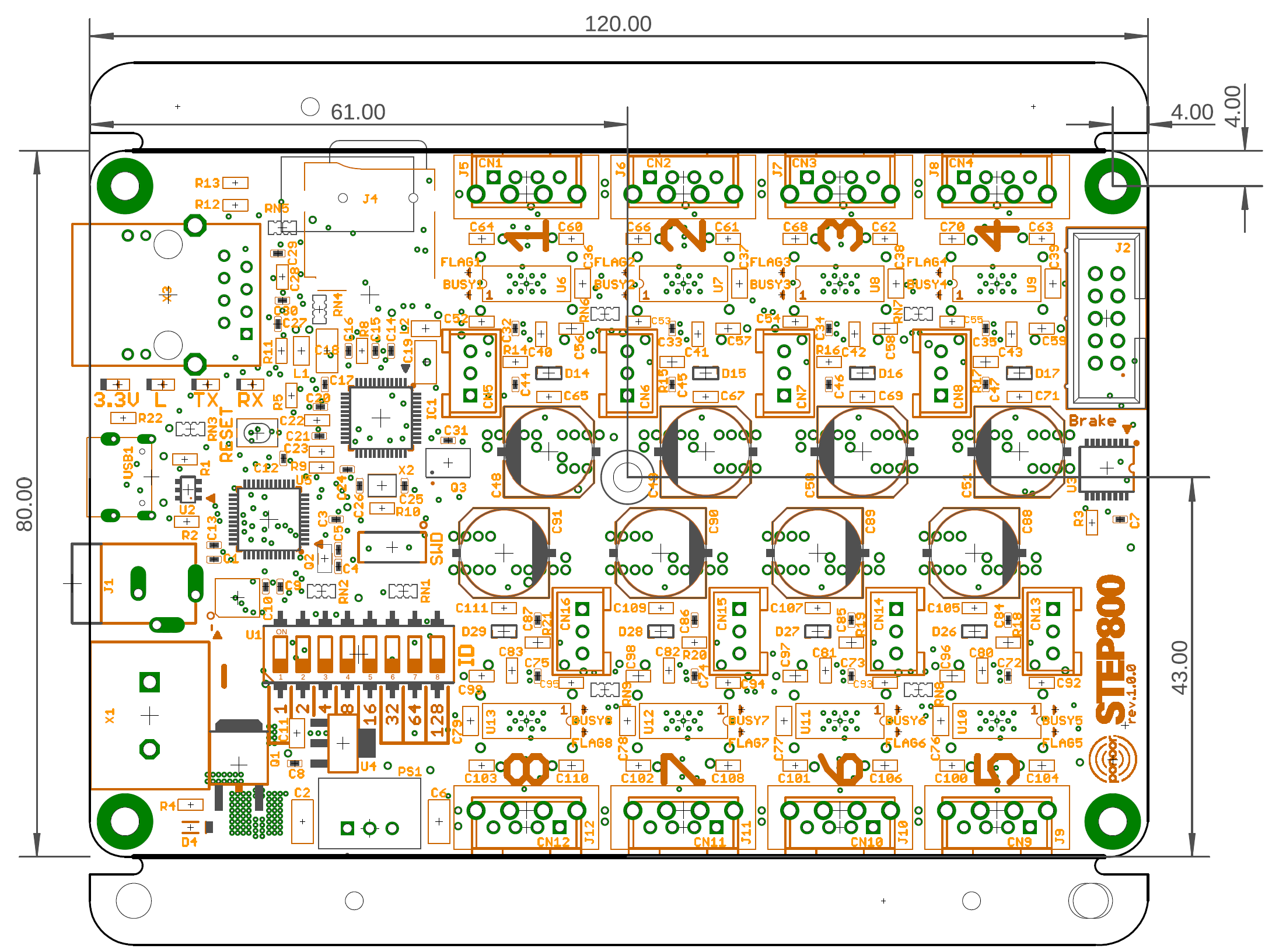
We also provide a PDF drawing of the board and it’s components for your convenience.
System
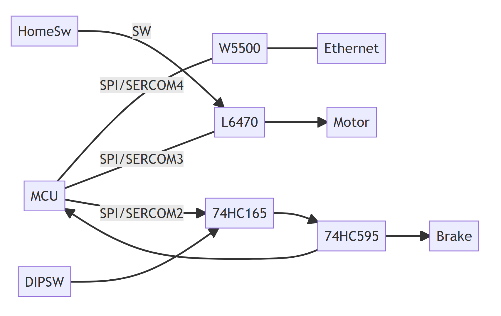
Like above, we also provide the wiring schematics of the board.
The primary components of the board are as follows:
Components |
Manufacturer |
Model number |
|---|---|---|
MCU |
Microchip |
|
Ethernet Controller |
Wiznet |
|
Stepper Driver |
STMicroelectronics |
|
DC-DC Converter |
ROHM |
Pin Assignments
Pin |
Function |
Notes |
|---|---|---|
D0 |
Shift Register SCK |
|
D1 |
NC |
Pad exposed in soldering side |
D2 |
Shift Register MOSI |
|
D3 |
Shift Register MISO |
|
D4 |
SD_CS |
|
D5 |
Shift Register ENABLE |
|
D6 |
L6470 MISO |
|
D7 |
NC |
Pad exposed in soldering side |
D8 |
NC |
Pad exposed in soldering side |
D9 |
NC |
Pad exposed in soldering side |
D10 |
W5500_CS |
|
D11 |
L6470 MOSI |
|
D12 |
L6470 SCK |
|
D13 |
L |
|
D20/SDA |
NC |
Pad exposed in soldering side |
D21/SCL |
NC |
Pad exposed in soldering side |
D22/MISO |
W5500_MISO |
|
D23/MOSI |
W5500_MOSI |
|
D24/SCK |
W5500_SCK |
|
D30 |
NC |
|
D31 |
NC |
|
D38 |
NC |
Pad exposed in soldering side |
A0 |
L6470_CS |
|
A1 |
NC |
Pad exposed in soldering side |
A2 |
L6470_RESET |
|
A3 |
W5500_RESET |
|
A4 |
SD_DETECT |
|
A5 |
Shift Register CS |
Note
Since the L6470_RESET and W5500_RESET are connected
independently to their respective chip’s reset pins, be sure to set
pinMode to OUTPUT and set each of the state pins’ to HIGH.
Pads on the PCB’s Rear Side
There are unassigned pins and power pads on the rear side of the PCB. They are 2.54mm pitch, so you can attach surface-mount pin headers and IC sockets. R35 and R36 can be used for the pull-up of the I2C data (SDA) and clock (SCL) pins. The chip size is 1608 (0603).
Since these pins are not implemented or controlled in the firmware we provide, it is on you to customize the firmware to implement the functionality you need.
SPI Assignment
The STEP800 uses different SPI ports for the PowerSTEP01 motor driver chips and the W5500 ethernet controller for easing control via the firmware. Here is a very informative guide about SPI allocation on the ATSAMD21.
W5500
Pin |
Function |
SERCOM |
SERCOM Alt |
|---|---|---|---|
D22/MISO |
MISO |
SERCOM4.0 |
|
D23/MOSI |
MOSI |
SERCOM4.2 |
|
D24/SCK |
SCK |
SERCOM4.3 |
Shift registers (DIP switch, brake output)
Pin |
Function |
SERCOM |
SERCOM Alt |
|---|---|---|---|
D3 |
MISO |
SERCOM2.1 |
|
D2 |
MOSI |
SERCOM2.2 |
|
D0 |
SCK |
SERCOM2.3 |
L6470
Pin |
Function |
SERCOM |
SERCOM Alt |
|---|---|---|---|
D6 |
MISO |
SERCOM3.2 |
|
D11 |
MOSI |
SERCOM3.0 |
|
D12 |
SCK |
SERCOM3.3 |
Clock
A 16MHz crystal oscillator is connected to the OSCIN of motor ID 1’s PowerSTEP01. From there, OSCOUT and OSCIN are daisy chained in order of IDs, so please set each PowerSTEP01 to External 16MHz input, Inverted Output (``EXT_16MHZ_OSCOUT_INVERT``). If the internal clock is used, gradual shifts in movement may occur during constant speed operation of the motors.
Unavailable PowerSTEP01 Features Due to Hardware Design
STCK
Since it is not wired, Step Clock operation is not possible.
ADCIN
This is wired directly to GND and is therefore unusable.