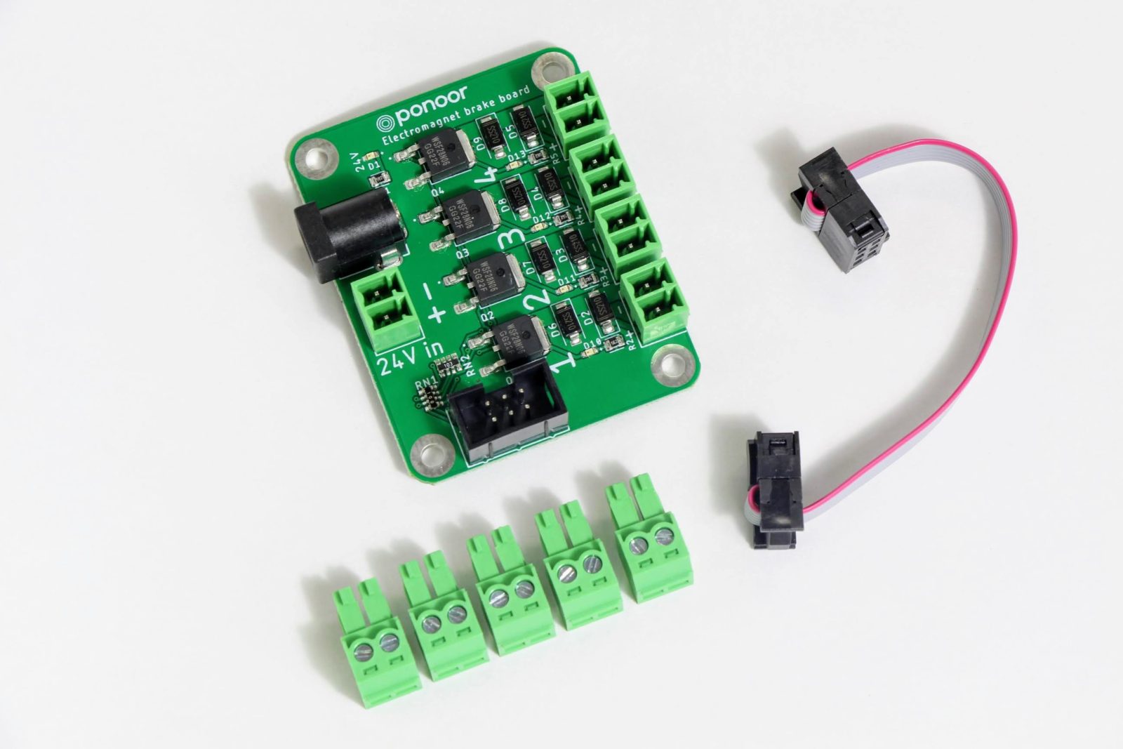
Electromagnetic Brake
About
Some stepper motors are made with an electromagnetic brake built-in. Typically, stepper motors have a holding torque which holds loads even when stopped; however, when power is lost, the holding force is lost and the suspended load will fall.
An electromagnetic brake is a device that locks the shaft of a motor and only releases when the shaft is energized. In the event of a power failure to the motor, the brake will immediately lock the shaft which prevents the load from moving or falling. Vertically moving loads should especially consider using one of these devices.
When using a stepper motor with an electromagnetic brake, it is necessary to release/lock the brake depending on the status of the motor. This brake add-on board is designed to be controlled in conjunction with the STEP400 motor controller.
Operation
What is an electromagnetic brake?
Some stepper motors have an EM brake built-in. In operation, stepper motors maintain a holding torque even when stopped. However, if power is lost, then that torque is lost and any suspended load will move or drop.
The brake is a device to lock the shaft when power is lost–or when commanded–and releases when power is regained–or when commanded. This device is especially necessary in situations of vertically suspended loads.
Response Timing
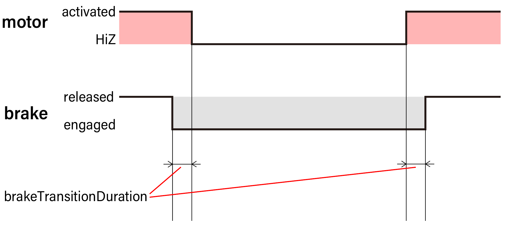
The EM brake locks the axis when the power to the brake is lost. However, this mechanism is not instant and requires a slight amount of time to engage. This means there must be a duration of time in which the brake and the motor are both engaged.
This transition duration, as it is called, does not affect how long it
takes for the brake to engage. This duration instead affects how long to
wait before releasing or engaging the motor after the brake. The initial
value of this overlap time is set to 100ms in the STEP400. It can also
be configured using the command /setBrakeTransitionDuration or from
the config tool.
Built-in EM Brake Examples
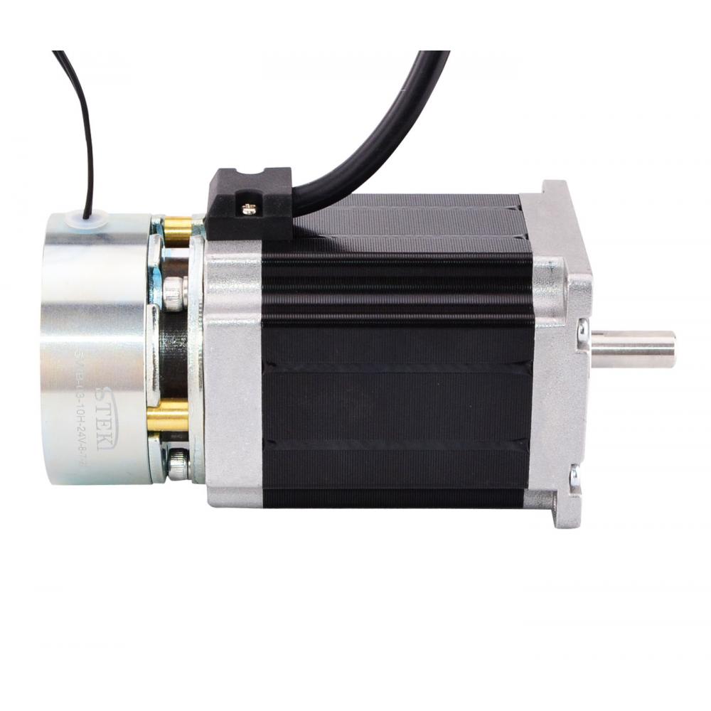
OrientalMotor PKP243D23M2
Wiring
Wiring the Power Source
Power Source Voltage
Supply power for the electromagnetic brake. Many EM brakes use 24V, but please refer to the datasheet of your motor.
Power Supply Terminals
There are two types of power supply terminals: the DC barrel jack and the Euro-style terminal block.
Warning
As these are connected on the PCB, DO NOT SUPPLY BOTH AT THE SAME TIME
DC Jack
Outer diameter 5.5mm
Inner diameter 2.1mm
Center positive
Euro-style Terminal Block
A 3.81mm pitch, 2pin Euro-style terminal block is built-in. Refer to the polarity described on the PC for connecting your DC supply correctly.
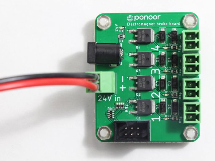
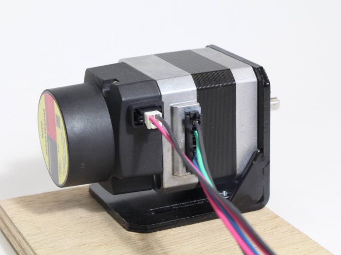
Connecting the Motor
Connect the wires from the EM brake’s terminal block to the corresponding motor. Note how each terminal on the brake is numbered just like the STEP400–make sure these match in terms of wiring.
Like most EM brakes, this brake has a polarity requirement, so wire your motor as stated on the PCB.
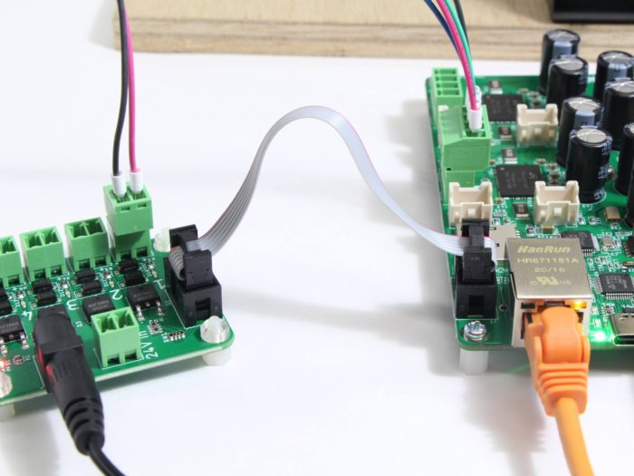
Connecting the STEP400
Connect the STEP400 using the provided 6-pin ribbon cable.
Sending Commands
Brake Mode
To use the electromagnetic brake, brake mode must first be activated. To
do this, send the command /enableElectromagnetBrake or from the
config tool under Electromagnetic brake enable.
If the mode is enabled, the brake will be controlled according to the motors’ excitation state.
Switching States
With the command /activate, you can switch the excitation state of
the motor. The brake will be released when the motor is excited and
engage when the motor is not excited.
The overlapping time Brake Transition Duration can be set from
/setBrakeTransitionDuration or from the config tool under Brake
transition duration.
Releasing the Hold
Any load will be releasing when the holding torque on it is lost.
However, there are cases where this behavior is desired. To do this,
the command /free can be sent.
Warning
Be very careful when sending this command. It is dangerous while any load is still attached to the motor! Ensure the load is safed before sending this command!
Command Behaviors
While the EM brake is engaged, the motion commands /run, /goTo,
and /move are not executed. Instead, the error
ERROR_BRAKE_ENGAGED message will be raised.
Note
Python users: This message will raise an error!
Commands that put the motor into a non-excited state (torque hold released) will behave as follows:
/softHiZ: Decelerate the motor to a stop, engage the brake, then release the motor (HiZ state)./hardHiZ: Stop the motor immediately, engage the brake, thenrelease the motor (HiZ state).
/softStop and /hardStop have no change in behavior and will
operate like normal. The brake is not engaged when these commands are
sent and the motor is kept excited.
Specifications
Basic Specifications
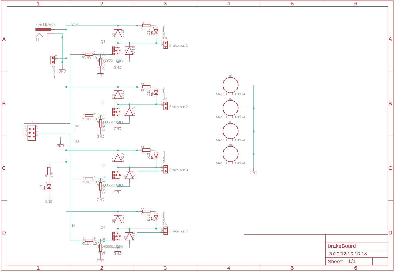
Input voltage: 5-48V
Control channels: 4 channels
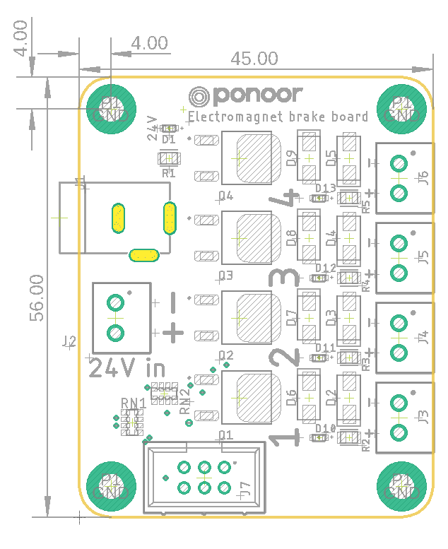
PCB size: 45x56mm
Note
When supplying voltage under 12V, the indicator LED may not be visible.
Driving Current
According the datasheet of the switching MOSFET, the rating is 60V @ 28A. However, the actual rating is limited to the rating of the power source terminal block which is 7A. Within this range, you can control other loads like LEDs or motors.
Drawings
Accessories
3.81mm pitch 2pin Euro-style terminal block x5
6 pin ribbon cable